
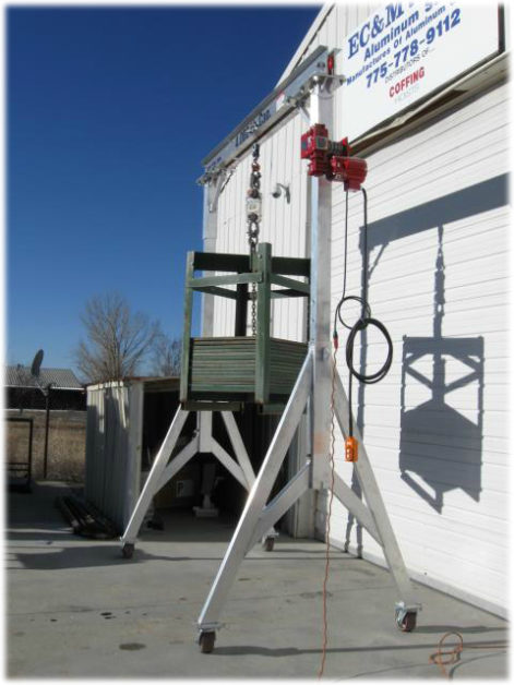
Custom Gantry Crane with Electric Winch
At first glance, this crane may not appear especially unique, but nothing could be further from the truth. Every aspect of this custom aluminum gantry crane was engineered around a highly specific set of customer requirements.
While we would have liked to identify the end user, we are prohibited from doing so under the terms of a non-disclosure agreement (NDA). What we can share are the engineering challenges that made this one of EC&MW’s most interesting and rewarding custom gantry crane projects.
Customer Design Requirements
Working closely with the customer’s purchasing department, the following requirements were established:
- 4,000-pound lifting capacity
- 110-volt electric winch
- Adjustable height with a maximum Height Under Beam (HUB) of 149-1/4 inches
- The narrowest possible footprint while maintaining a safe height-to-width stability ratio
- An 8-foot beam with a fixed, center-mounted sheave point
Individually, none of these requirements presented a significant engineering challenge. However, combining all of them into a single crane design required innovative solutions where solving one problem often introduced another.
The goal was to satisfy every requirement without compromising structural integrity, lifting capacity, stability, or operator safety.
Solving the Headroom Challenge
Achieving the required 4,000-pound lifting capacity was relatively straightforward.
The real challenge was the customer’s limited headroom.
A conventional aluminum I-beam could not be used because there was insufficient clearance to route the winch cable beneath the beam and connect it to a pulley mounted on the lower flange of a standard I-beam. Although the required capacity could easily be achieved, the available headroom made a traditional beam design impossible.
A Custom Dual-Channel Beam Design
To overcome this limitation, EC&MW engineered an entirely different lifting member.
Instead of using a traditional I-beam, the crane utilizes two parallel 8-inch aluminum structural channels bolted together with multiple precision-machined spacers.
This custom beam assembly provides exceptional rigidity while creating an open center section that allows the sheave to be mounted directly in the center of the beam.
This innovative configuration provided:
- The required cable routing
- Maximum lifting height
- Clearance for the winch cable
- Full 4,000-pound rated lifting capacity
- Required engineering safety factors
Adjustable Height Without Compromising Stability
The next engineering challenge involved the crane’s adjustable-height design.
As the crane height changed, determining where to mount the electric winch became a critical structural issue.
Mounting the winch on either the base or adjustable vertical columns would have introduced significant outward pulling forces into one upright. This additional side loading would have increased leg splay beyond acceptable engineering limits and failed structural analysis.
Both mounting locations were quickly eliminated.
Top-Mounted Winch Design
The solution was to mount the 110-volt electric winch directly to the crane’s top cap assembly.
Positioning the winch at the top of the crane kept the pulling forces aligned with the primary structural members instead of introducing unwanted side loads into the adjustable uprights.
This design offered several advantages:
- Eliminated excessive leg splay
- Maintained structural integrity
- Preserved crane stability
- Allowed full adjustable-height operation
- Maintained lifting performance throughout the crane’s entire height range
Engineering Around Wire Rope Fleet Angle
The final challenge involved proper wire rope spooling.
Fortunately, the customer’s application did not require lifting from a pit.
Because the distance between the winch drum and the first sheave was less than 24 inches, the wire rope could not spool correctly using a standard winch configuration.
Proper wire rope performance requires maintaining a fleet angle of approximately 1° to 1.25°. With such a short cable path, achieving this geometry was impossible without modifying the winch.
Custom Winch Drum Modification
EC&MW solved the problem by manufacturing and installing custom drum filler sleeves on both sides of the winch drum.
These sleeves reduced the available spooling width, allowing the wire rope to maintain the proper fleet angle throughout operation.
The wire rope was also shortened to match the modified drum capacity.
While this reduced the crane’s available lifting travel—making it unsuitable for pit applications—it ensured:
- Smooth cable spooling
- Consistent lifting performance
- Reduced uneven cable buildup
- Longer wire rope life
- Improved long-term reliability
Engineering Every Detail
Although this crane appears relatively simple at first glance, every major component was custom engineered to satisfy a specific customer requirement.
From the dual-channel beam configuration and top-mounted electric winch to the modified drum assembly, every solution addressed a unique engineering challenge while contributing to the crane’s overall performance.
The finished product demonstrates how innovative engineering can overcome seemingly conflicting design constraints while maintaining the safety, structural integrity, durability, and dependable long-term performance that customers expect from every EC&MW custom aluminum gantry crane.
Buy a Custom Gantry Crane
Want an aluminum gantry crane like this one or have one custom-built for your project? Contact us for a quote.

